I'ts been some time since I last wrote about the GH60 project and much more than I had thought has changed since then.
The rev. A prototype was to be just a testing board to make sure everything works all right before we run the actual group-buy, but in fact the number of changes and extra features added since then was so large that the rev. B is actually a new board.
In this post I'll try to quickly present the changes, new features and design decisions that make the (hopefully) final version of this 60% programmable keyboard.
Bugfixes
I mentioned a couple of errors I made in rev. A in the first post about the project, and of course all of them are now fixed.
Some of these errors, like the wrong position of C3 or lack of some silkscreen legends were obvious and easy to fix, but the rest did bring some more problems and required a certain dose of compromise.
One of the most annoying problems of the previous version of the PCB was the necessity to mount some of the switches rotated 90 degrees. As unimportant as it could seem, it is an actual problem. During a discussion on geekhack someone brought to my attention the fact that the Cherry MX switch stems are not perfectly "cross-shaped", as I had previously thought. And this caused keycaps to mount very tightly on the stem making it very hard to remove the keycap and introducing a potential risk of breaking the keycap stem.
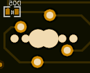
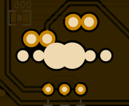
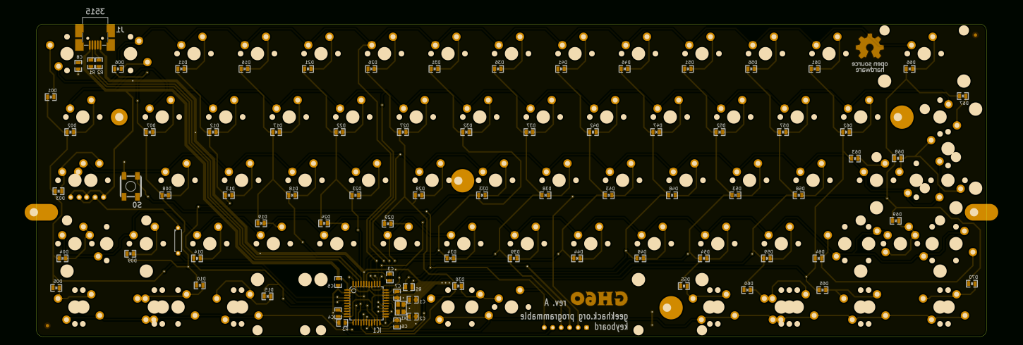
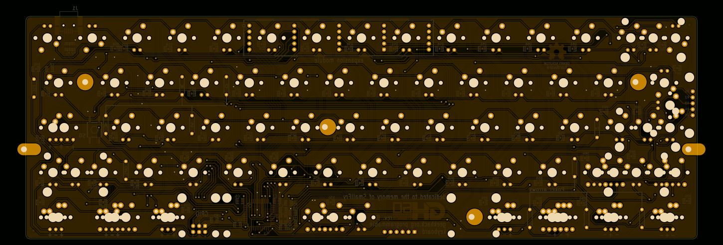
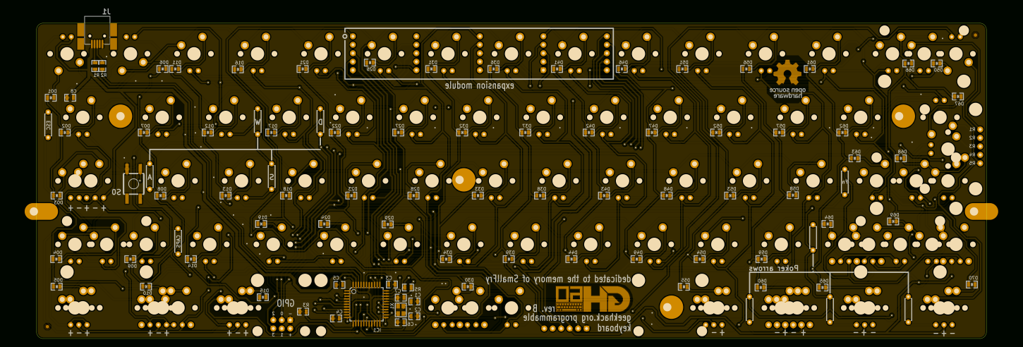
Since we obviously didn't want this to happen, I decided to put all the switches either in their regular orientation or rotated 180 degrees (which shouldn't be a problem - a lot of keyboard manufacturers do it anyway). This decision resulted in overlapping pads, but because there had already been some overlapping pads, I just decided to agree with it. You can see the previous version on the left and the new one on the right. In the end it's not that bad.
When making the rev. B I also fixed some dimension and hole position problems, like the stabilizer holes being too close to PCB edges and the USB connector slightly misplaced. I'm still not sure all the dimensions and positions are correct and I'm afraid I'll only find out when I finally get my hands on the final prototype. Then I'll be able to tell what kind of final corrections we'll need to make sure it fits everything well.
I have to say that measuring the Poker PCB, the case and making sure everything fits together was probably the hardest part of the work. A lot of problems including a wrongly scaled ruler made it even harder to debug the previously designed board, which I thought had already been correct. Each time I was sure everything was done properly, it appeared there was something more I had not taken into account. And when I finished it still appeared that the measurements made by other people were slightly off. That may have been due to differences in cases (which is totally possible - the tolerances aren't that great for plastic cases) or simply differing tools. Anyway, I'm hoping to get to know if the board is OK soon.
New features
The main reason to practically redesign the whole board was the number of new feature requests. Some of the ideas were incorporated into GH60 and I'll quickly present them here.
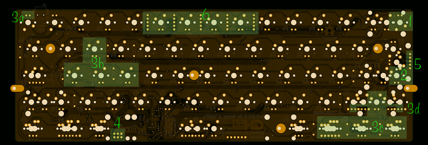
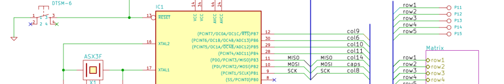
- Split backspace option (1) - this was probably one of the most frequently requested features (well, maybe after backlighting), as it adds the only missing switch position which allows to replicate the HHKB layout. I decided to connect this extra switch to some unused matrix intersection in the lowest row, namely column 10, row 5.
- Split enter option (2) - I added one more switch position for enter to make it possible to implement a split enter option, where the ANSI enter key is 1u shorter and there's one more regular key in the home row (that key already has a footprint, because it's available in the ISO layout anyway) - you can think of this enter key as the ISO enter key with the top part cut off.
- Extra backlit keys (3) - since it wasn't possible to have a backlighting option where every LED can be controlled separately (extra chips just wouldn't have fit), I decided to at least use the 4 remaining JTAG pins and wire them to additional LED clusters: w-a-s-d (for gamers), Fn key on the right, "poker arrows" cluster (to light up the keys which change to arrows for Poker fans) and the escape key. Those clusters will be independently settable by the firmware.
- Matrix rows breakout header (5) - all 5 row signals of the keyboard matrix are available as pads where you can solder a header or wires directly. This together with the expansion port makes it possible to connect up to 20 more switches or the GHPad board. In this case the GHPad will not have to have any chips on board except diodes and it will extend the GH60's matrix instead of acting as a separate keyboard. This option is mainly for those who want to put the two keyboards in a common case and it blocks the backlighting option and 4 clusters of controllable LEDs since it uses the same signals.
- Full backlighting LED matrix - I added traces which make it possible to add full backlight to the board, this requires an add-on module, however.
- A footprint for an expansion board (aka add-on module) (6) - this can be the backlighting controller or any other extension module ever designed in the future, for example a bluetooth dongle. It sits under the board in the central top area. The signals available are: 14 LED columns, 5 LED rows, 4 general purpose pins (the same JTAG pins as used for LED clusters or GHPad columns) and power (VCC and GND).
LED backlighting design considerations
The GH60 keyboard was to be a non-backlit keyboard from the beginning. In fact the lack of backlighting capability was one of the assumptions which was to simplify the whole board, but because of high demand I did decide to change that in rev. B. There were a couple of ways of implementing this feature, each with its own pros and cons.
One of the propositions I got on the forum was to just put pads, so that the used can solder the diodes firmly and then wire all of them individually. This was of course my fallback option if everything else failed, but I decided to try to do something better.
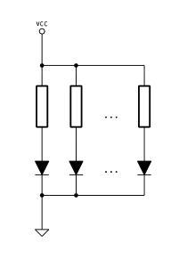
The next simplest option was probably to connect all LEDs in parallel. However, this has one important drawback: every LED needs it's own current-limiting resistor. Unfortunately, problems don't end here. The value of this resistor depends on the type of diode, so the brightness would either depend on the type of LED (color first of all) or I'd have had to add a high-power transistor to implement PWM control. Needless to mention the extra cost of pick-n-place time to solder all the resistors. Too many disadvantages, and no extra features, so I decided to think more.
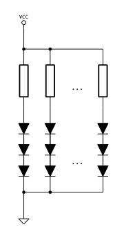
The other option was to do it as it's done in most LED lighting systems, which is a mixed (serial-parallel) topology. Here, we substitute each LED from the previous solution with a few of them connected in series. The number of necessary resistors drops, but also the required voltage rises. If the supply voltage is chosen in such a way that the voltage drop on the resistor is similar to that of the previous circuit, the total power dissipated in the resistors is obviously lower (n times where n is the number of resistors in each series pack). Since putting a step-up converter on the board to pump up the voltage from USB's 5V was rather a no-go, I forgot about this option very quickly.
And then I decided to go with what seems to be the most beefed-up version of backlighting, namely matrix based circuit with multiplexed rows. It incorporates some advantages and some disadvantages of the previously shown solutions, but it has one nice feature they don't have - it gives the opportunity to control every LED separately if appropriate circuitry is provided - and this results in endless modding capabilities. Because in this approach only one row is lit at a time, only 14 (number of columns) resistors are required, that's less than in the parallel-series solution with 3 LEDs in each series. The necessary switching circuit is of course more complicated that just a voltage booster, but since neither would have fit in the board nicely, I knew I would have to make a separate module anyway, so I chose this option. I also decided to put the current-limiting resistors in the expansion module not to add more components to the board any more. I don't know how I'll fit everything in this module yet, but I will have to, somehow.
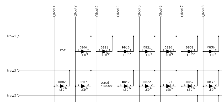
I connected all the switch LEDs except those which are already connected in directly controllable clusters, so assuming that the backlight module will require only one wire to communicate with the main microcontroller, it's possible to have nearly all the diodes separately controllable. The exceptions will be those connected in clusters (w-a-s-d and Poker arrows) - only the whole cluster can be turned on or off; and one of the other directly connected LEDs, since one pin will have to be used for communication with the module. If someone is very inclined to have fully independent lights, they can always cut the traces of the LEDs already connected to the microcontroller and wire the proper LED matrix intersections to the respective diodes, including the one which will have to be disabled due to its use as a communication pin. That would be some serious modding, but it's surely possible.
Other changes
The board has also changed in a few more maybe less important aspects. One of the changes is ground pour also on the top layer (the previous version only had it on the bottom). In fact I don't know what drove me to that decision in rev. B, but since the highest frequency present in this design is 16MHz and it's just microcontroller clock, I don't really think it matters for signal integrity. Now the ground pour is on both sides and it looks pretty.
I also changed some of the drill sizes and pad annular rings to simplify soldering by hand and I fixed the mounting hole positions hoping that they will be fully correct this time. The official logo was designed and picked by the geekhack community, so I also incorporated the new design into the board.
Most of the changes introduced are documented in the github issue system. Please check it out for more information.
Here you can see how the keyboard's PCB has changed between rev. A and rev. B:
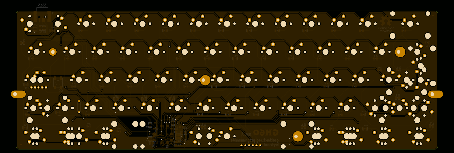
You can also download a package with hi-res images.
Next steps
The rev. B board is in prototype production now. The prototype is scheduled to ship on the 22nd of August. When I get it, I'll be able to fix any minors errors and then finally start the volume production of rev. C for the geekhack group-buy.
waiting for RevC 🙁
Man am I regretting just hearing about this now. I just decided to build a custom keyboard earlier today, and I'm really bummed I missed the GroupBuy.
I'm planning on going with the KBT Pure layout, or something like it so I get a few extra keys. Then I'm going to solder the pads to some larger DIPs I've got lying around, and use them to control the LED zones, toggle a capslock and control swap, and toggle a qqwerty and Dvorak swap.
Another idea is to use a 4th switch to toggle disabling the LED controls in favor of using those Aux JTAGS for a Bluetooth adapter, but where would I put the batteries? I kinda wish you went with the Teensy 2++, so there was support for more LED zones, the GHPad, possible Bluetooth, and <a href = "https://www.pjrc.com/store/dev_display_128x64.html" title = "this"> dumb screen thing, but then it probobly wouldn't have fit in the same case'.
What do you think komar? I'd love to hear your thoughts.
Hi,
the batteries will have to go somewhere between the PCB and the (bottom part of) the case.
If the bluetooth module is used, I'm not sure how many LED clusters will be still usable. Probably at least 2 pins will be necessary to communicate with BT, so just 2 of 4 LED clusters will remain usable.
Using the otherwise unused pads to control layout is a good idea, but it won't be possible to switch between LED clusters and BT. If BT is connected, it'll just take some of the aux pins and it won't be possible to use them for LEDs any more.
Dear Komar,
Don't know what happen, by accidently, my GH 60 lost all all key function. I tried to re-map the key, but somehow it doesn't work. On libusb, there isn't ay device with vid = 16c0 and pid = 047c. All my device are vid= 0xFEED and pid = 0x6060. I tried to choose the device with name " Interface 1 " however when I hit the program on guy.py, the cmd said " Run Time Error: no device found " .
Is there any advice ? Please help me.
Thank you for your time.
Jay
The discussion on this problem starts here: https://geekhack.org/index.php?topic=37570.msg1550676#msg1550676
I see you don't monetize your website, don't waste your traffic, you can earn additional cash every month because you've got hi quality content.
If you want to know how to make extra $$$, search for:
Boorfe's tips best adsense alternative
Hi Komar,
I got the rev.C pcb, and I can't figure out the polarity for leds, and the default location for 'fn' key. I usually split up right shift bar into 1.75 shift and 1u fn on the right. If I stick the led into that fn key will it work?