This is just a quick build log of my super-simple dimmer for a LED strip while I'm working on the second part of How to make a keyboard.
I needed a very simple LED dimmer for a short piece of LED strip I'm going to mount in the cupboard. A quick google images search for "555 pwm" led me to this idea by Giorgos Lazaridis: An LED Array PWM Dimmer with the 555.
Here's the schematic of my version:
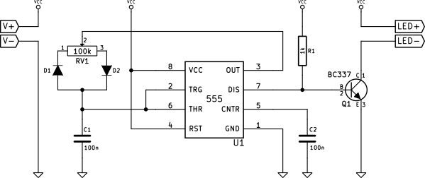
The circuit is rather simple. It's powered from a 12V supply. The 555 timer works in its regular astable mode, where pins 6 and 2 (Threshold and Trigger) are shorted and are used to sense the voltage across the capacitor C1. The charging/discharging circuit is, however, different than usually. In order to achieve a reasonably stable frequency, the sum of charge and discharge times must be independent from the duty cycle setting. For this reason, the capacitor is charged and discharged using the two complementary halves of the pot RV1. Because these two virtual resistors have to be connected to the same capacitor pin, diodes must be used to ensure the current flows only through the right part while charging and only through the left part while discharging.
The capacitor is both charged and discharged using pin 3 (Output), because it is capable of both sinking and sourcing current. When Output is high, the current flows through the right half of the pot and D2 and charges the capacitor. When the capacitor is charged to approximately 2/3 of supply voltage, Output transitions to low and the capacitor is discharged through D1 and the left half of the pot. When the capacitor voltage drops below approximately 1/3 of supply voltage, Output transitions back to high and the capacitor is charged again.
Pin 7 (Discharge) is used as this circuit's output, and its state follows that of pin 3 (Output). Because this pin is an Open Collector output, it needs a pull-up resistor R1. When it's low, the resistor wastes about 12mA of current. When it's high, the resistor limits the base current of Q1, driving it to saturation, which in consequence turns the LED load on. This means that the LEDs are on while C1 charges and off while it discharges.
Building
After building a breadboard prototype and verifying that it works, I decided to keep the size as small as possible and built the circuit without any PCB by directly soldering wires together.
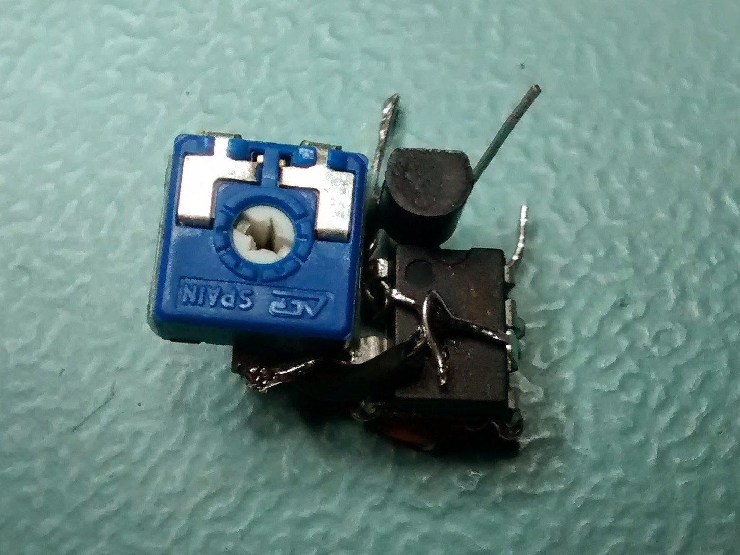
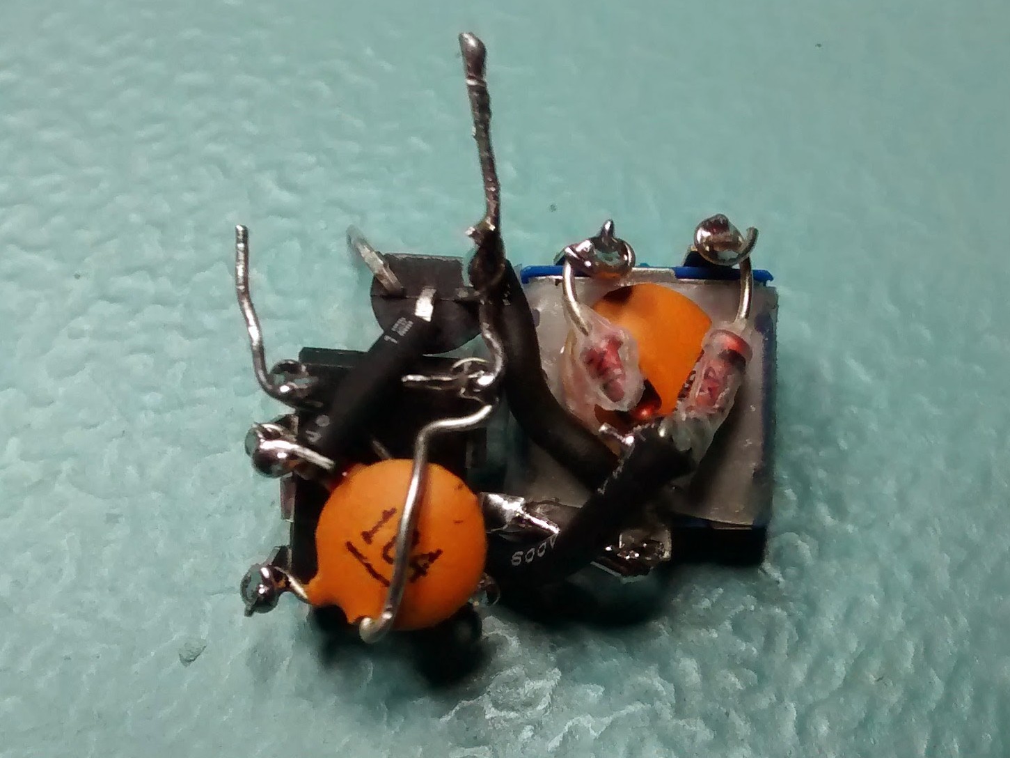
I managed to put R1 and C2 under the 555's dip package and also make some extra connections using the remaining component wires. Then I squeezed D1, D2 and C1 under a pretty large pot I happened to have. It was necessary to use some heat-shrink tubing to protect some wires from shorting. I also protected the pot's stem with a bit of adhesive tape (sticky face up), so that the hot-melt glue I was going to use wouldn't prevent it from turning. Next, I connected the two bundles together (Output to the remaining pin of the pot and C1's sense line to Trigger and Threshold) and added the transistor.
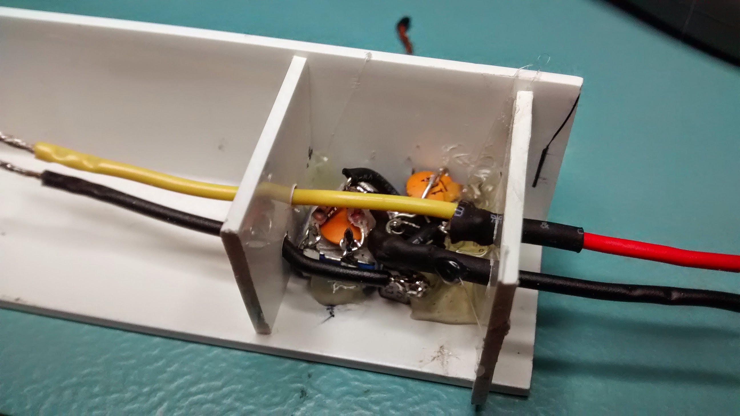
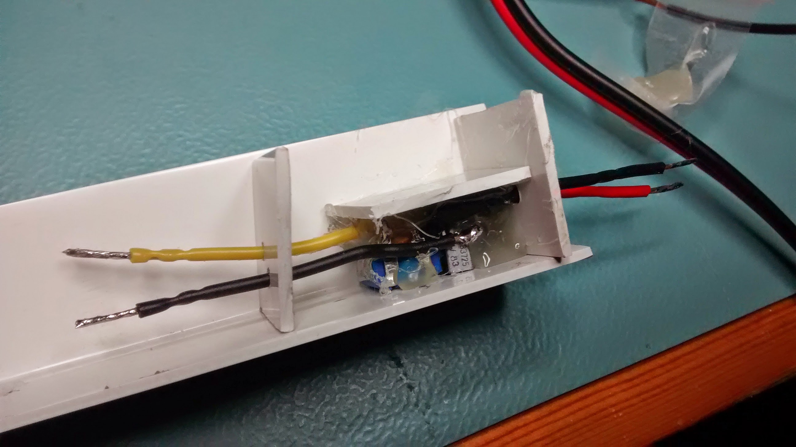
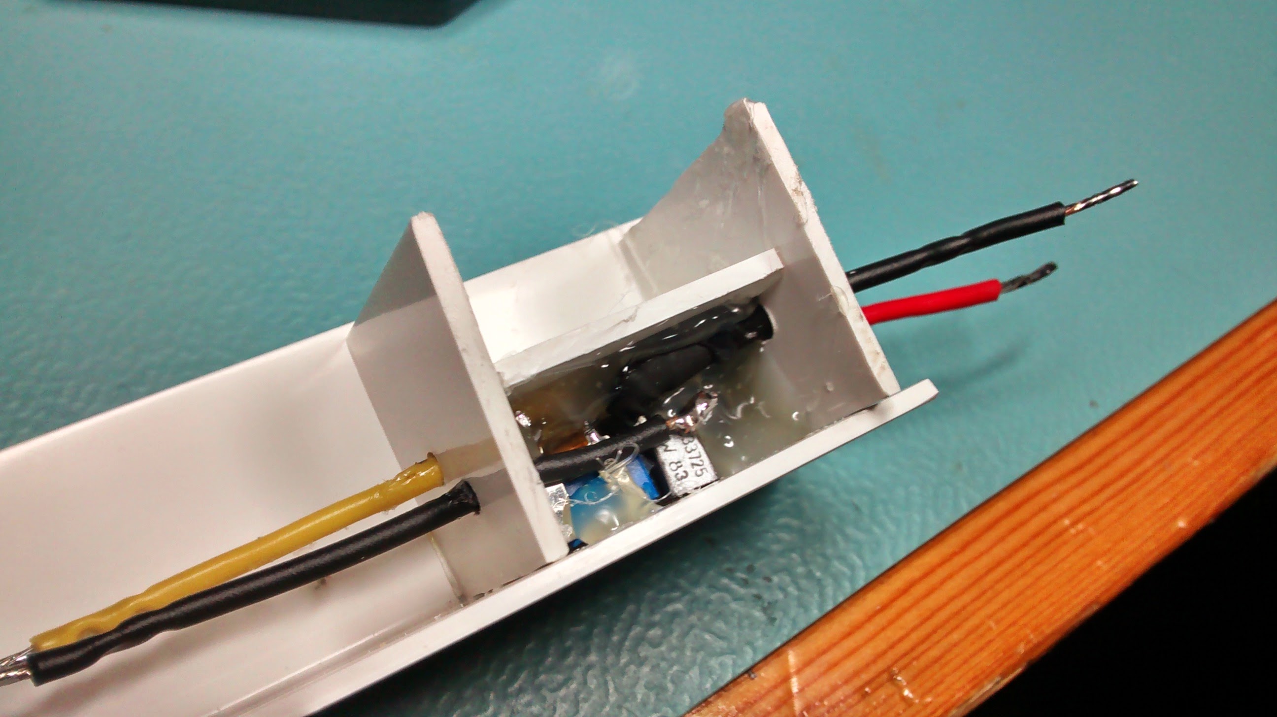
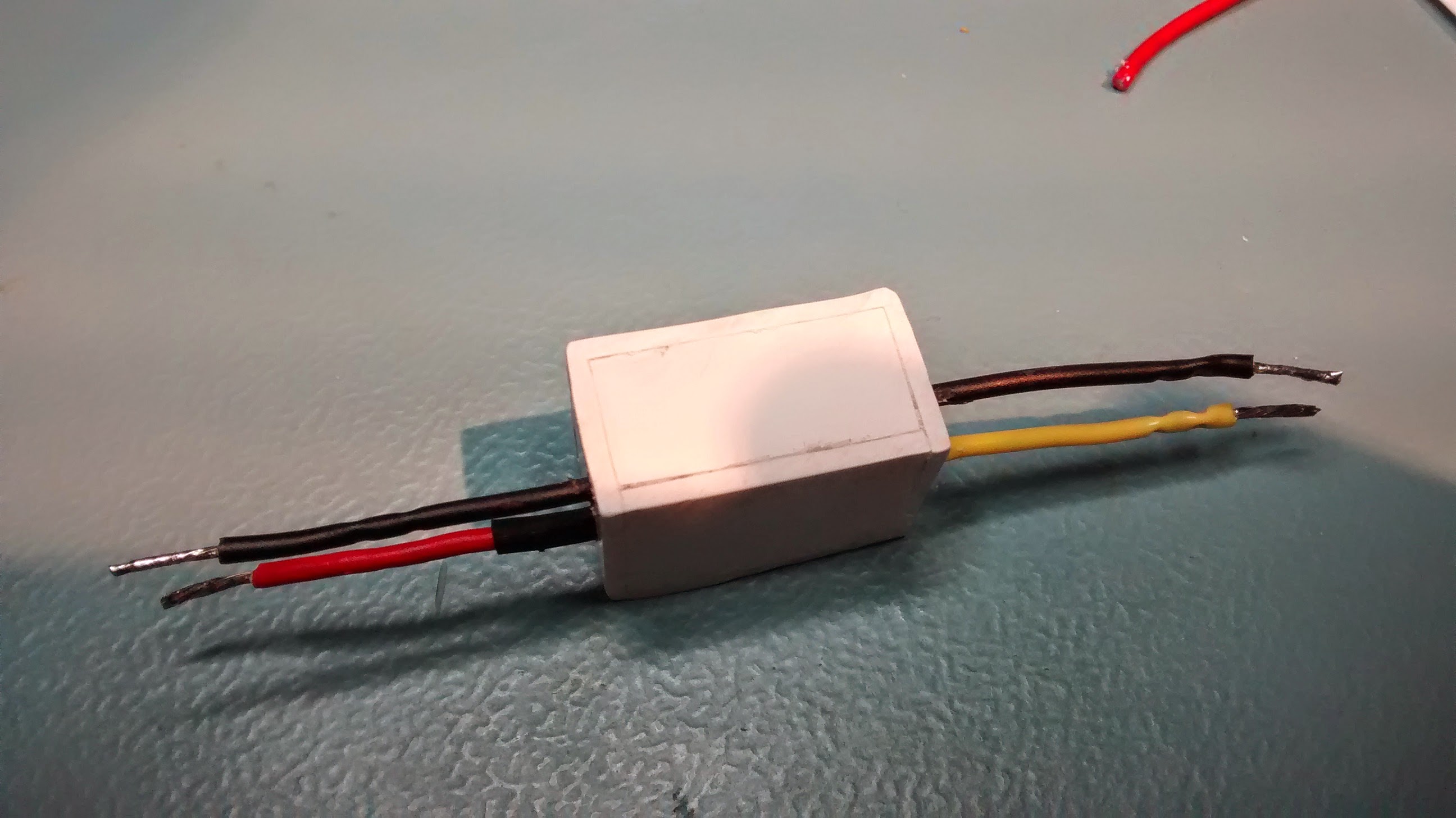
The next step was to solder the 4 connection wires and build a mini plastic case. I decided to use a plastic angle bar to form 2 walls of the case. I cut the two next walls out of the same plastic, drilled holes for the wires and squeezed the circuit between them. Then I applied hot-melt glue to temporarily connect the pieces together. In the image on the left the pot is laying face down and there's a hole in the angle bar to allow for brightness control. After the left wall fell out for some reason, I added the top one and filled everything with even more glue, treating it as a (very poor) potting compound.
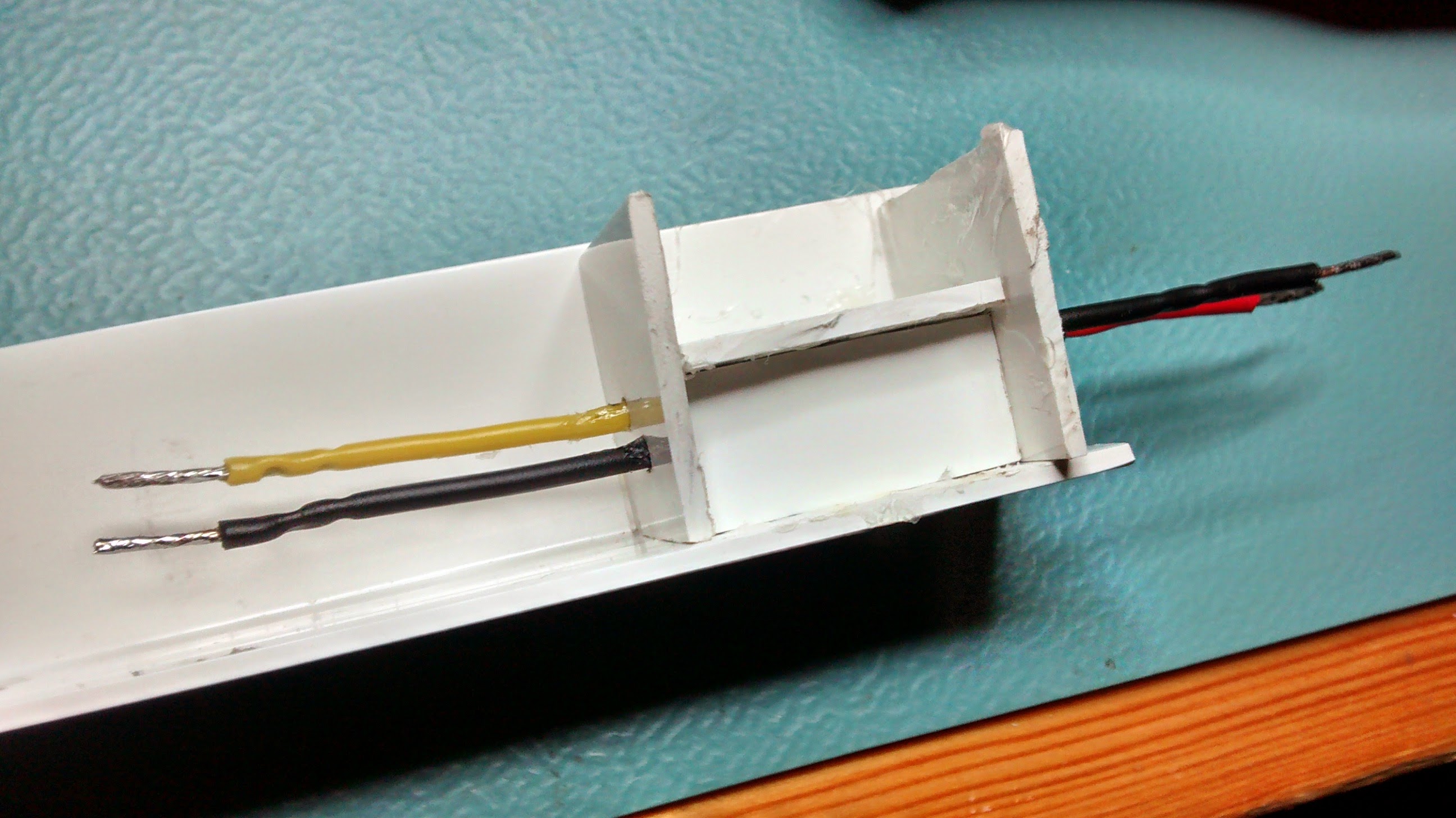
I re-added the left wall, filled everything with as much glue as I could and pushed the precisely crafted front wall inside. Making this wall required some patience as I wanted it to fit very tightly to make sure there were no holes.
The final step was to cut all the remaining bits of plastic and make the whole device into a nice box. I used a drill with a grinding disc to cut the plastic and then sandpaper to finish the rough edges. This took a while but I was left with a not-very-nice-looking final product which I'm still pretty satisfied with. Below, you can see pictures of the final stage:
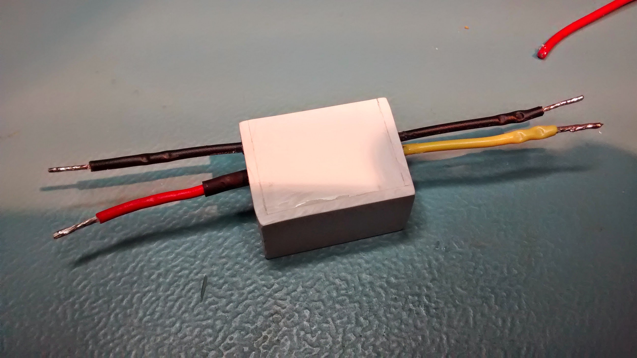
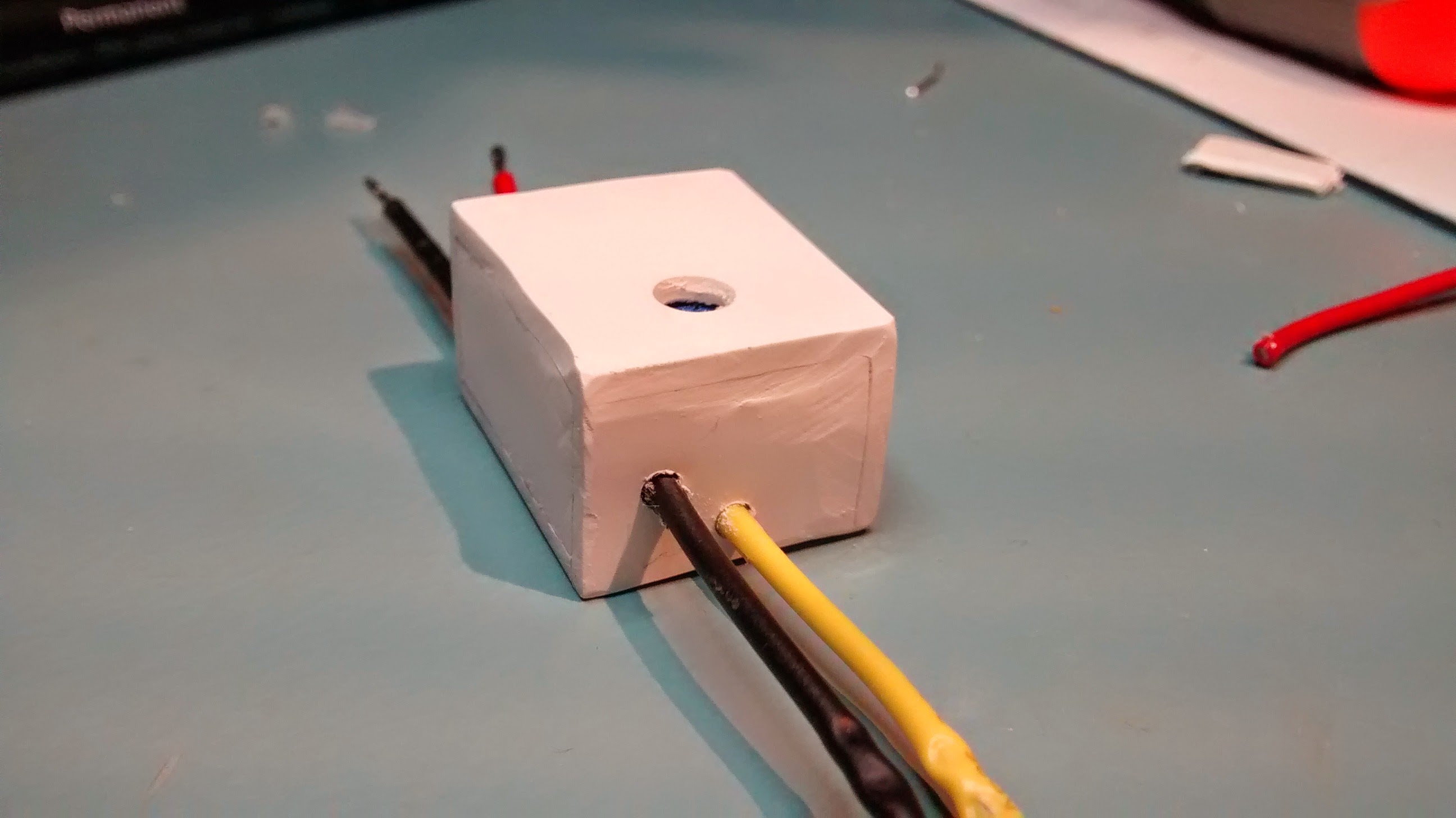
As you can see, it's not a very pretty device, but hopefully it will work. Now I'll wait for the LED strip to arrive to check it. My only concern is that when the transistor gets warm it might start to melt the glue, and then the whole thing might fall apart. But time will show...
Testing
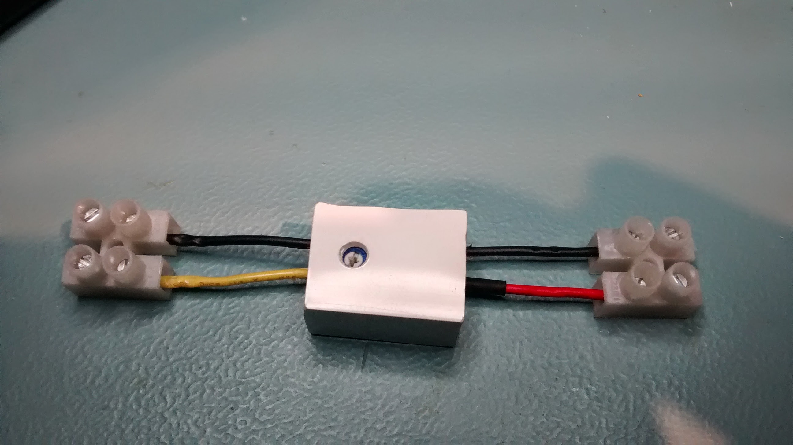
I hooked the dimmer up to some 3 white LEDs and a limiting resistor to test if everything worked okay.
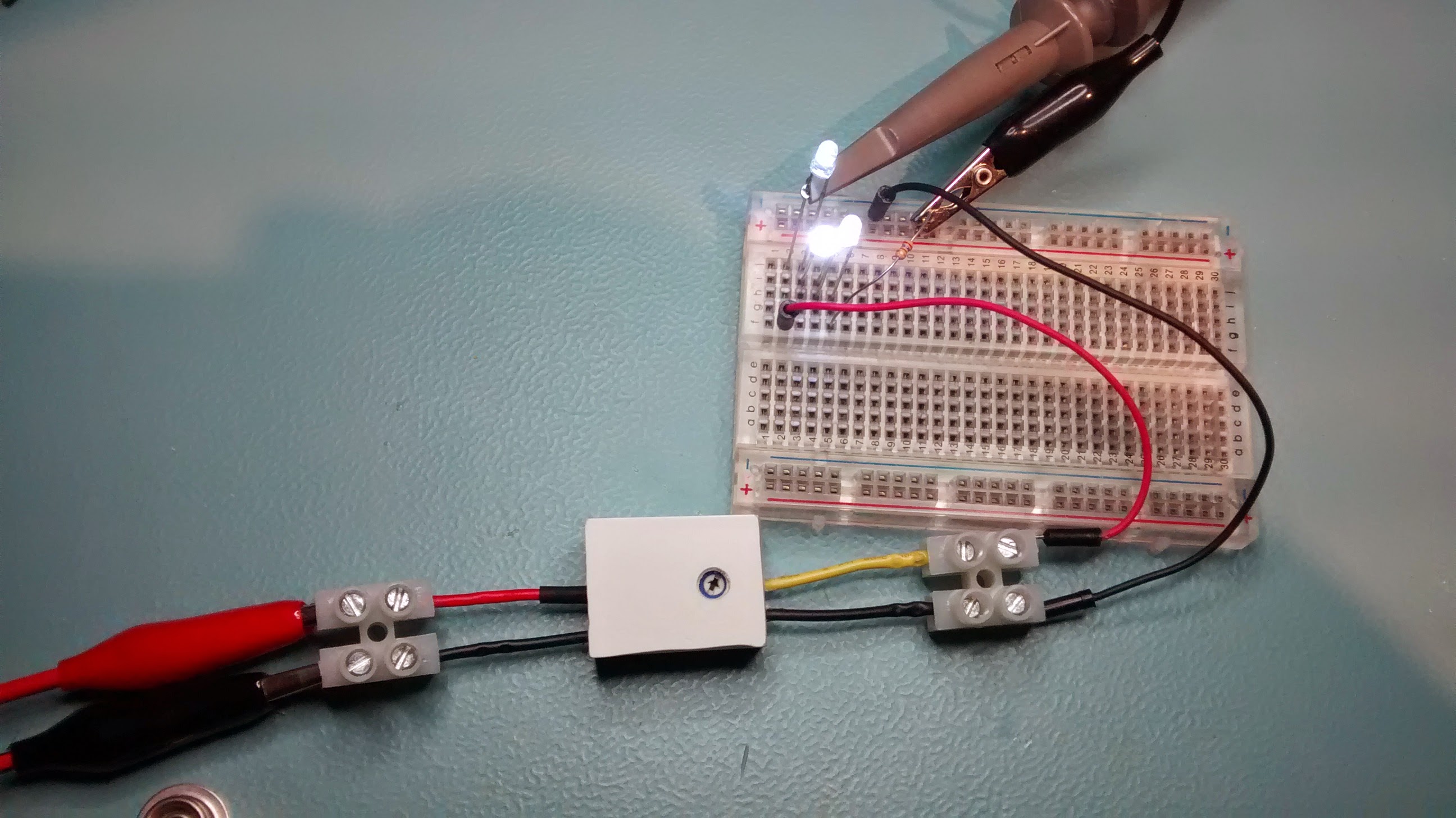
It did;)
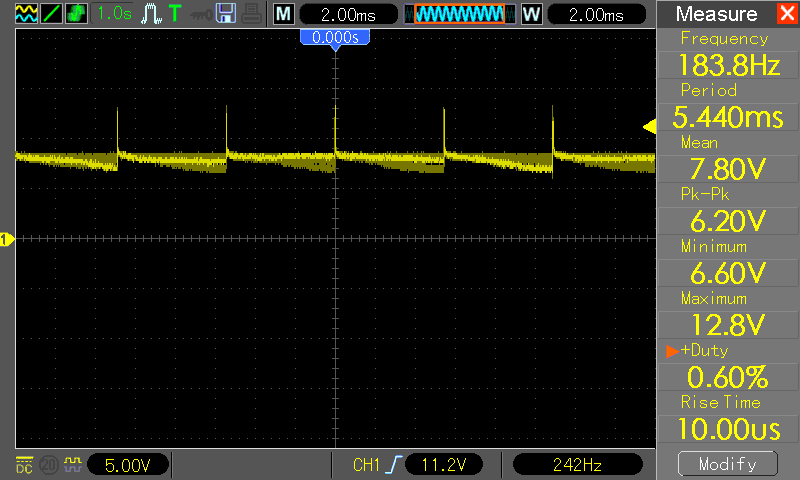
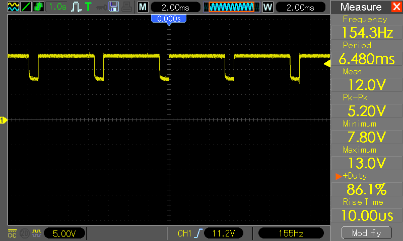
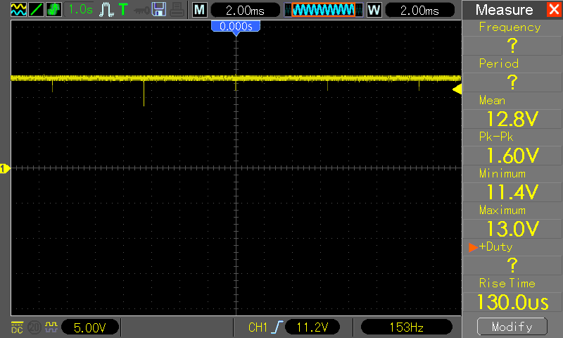
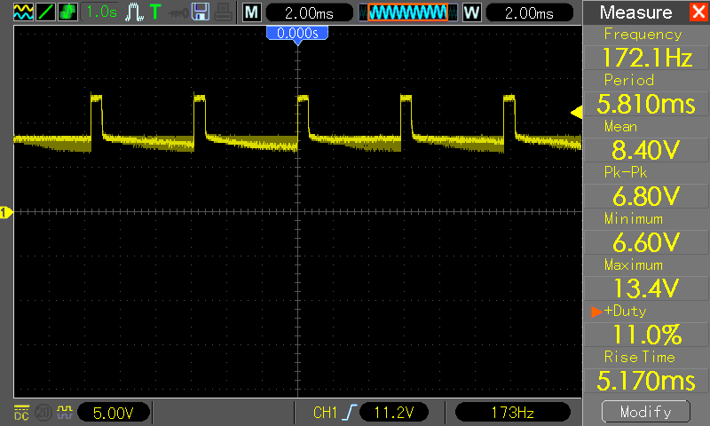
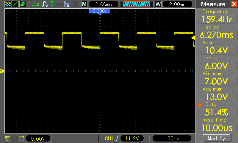
On the right side I present the voltage plots of the LEDs and resistor in series. As you can see, the frequency changes a bit with the duty cycle (the lower the duty cycle, the higher the frequency), but it's still within acceptable range. You can also see the plots for the edge positions of the pot (minimum and maximum brightness) on the left.
Hi Komar.
Could you modify this circuit to fade in a few power LEDs when powered on and fade out when disconnect power source?
I'd like to use it with a DIY aquarium LED light to simulate sunrise and sunset.
Hi Tomas,
you can't fade the LEDs out after power is disconnected unless you store the energy in some large capacitor (or very large, if you have power LEDs).
For a start I'd just try connecting a large capacitor in parallel with the LEDs and experiment with the capacitor's value to see what dimming times you get.
If that's not enough, I'd probably go with a small microcontroller, like attiny4 for example to control the LEDs with PWM and at the same time turn the lights on and off automatically at specific times.
Hello, Komar!
Can you tell me please, is it possible to make automatic emergecy lighting by myself? I mean that I want to redo it from my old one. I have this hardware.be/noodverlichting/van-lien/aqualux/1142051.html and I have already installed relay there to protect it from fire. However I want to improve it more!
what is value of D1 and D2?