Tutorial parts: 1 matrix | 2 controller (coming soon) | ...
Update (May 2016): check out the Russian translation: Как сделать клавиатуру — Матрица!
This will be the first and hopefully not the last post in the keyboard series. I'm hoping to make this a keyboard building tutorial from the ground up. Today I'll cover digital I/O and keyboard matrices. Equip yourself with some basic knowledge of electronics from school and let's get started.
Why matrix?
So how and first of all why do we make a matrix? Well, the most important reason is physical limitations of microcontrollers we use to make a keyboard. Microcontrollers and programmable logic chips grow with the number of pins, and growth means more power, capabilities and most of all higher price. So in the end you can either get a cheap chip with little capabilities (and that's what you need) but with few input/output pins, or a more powerful chip, which is much more than you need. And only with such a large chip do you get enough pins to drive a keyboard.
It has been regular practice in electronics for decades to extend the number of available communication options of processors and controllers in various ways. One of such ways which works well for mechanical contacts (switches) is making a matrix. In order to explain how a matrix works, some basic background will be necessary. Please revise the Ohm's law before continuing.
Some theory
In order to understand how digital electronics works, you'll need to understand 2 basic principles:
Principle one is that there is no concept of sending or receiving anything in communication. What you do to make 2 devices communicate is merely connect their pins with a conducting material. Then you can assume that the state of this material (voltage and current) will be the same on both sides. This is obviously not true in real life, but with slow communication and short conductors it works well that way. So in fact, sending and receiving information becomes sharing information.
On the transmitter side you just change the electrical state of the conductor (by coercing a constant current or voltage), and count on the fact that the receiver will be able to detect that change and understand it in a proper way.
This principle also implies that there is no connection between the direction of communication and the direction of current flow, which is a mistake a lot of people make which prevents them from understanding how electronics works.
When you want to "send" a "0" logic state, you'll usually do it by causing the voltage to be 0V, this means that the current has to flow into your transmitter for the receiver to be able to tell it's a "0" (since the opposite direction of current flow would be possible only if there was a negative voltage anywhere in the circuit, and that is generally not true for digital electronics). On the other hand, when you "send" a logic "1", you usually represent it by the same voltage as supply voltage, and because this is usually the highest voltage in the circuit, the current has to flow out of your transmitter.
Principle number two says that there is no way to read a state of a conductor without modifying this state. No matter whether you want to read voltage or current, you need electrons to flow through the device you're measuring with. Electron flow means current flow, and current flow means that the currents and voltage change in the node you're measuring (refer to the Kirchhoff's circuit laws). This implies that if you want to "send" information by changing the state of a pin connected electrically with another pin, you have to be able to maintain this state, that means meet all the conditions imposed by the receiver.
The switch
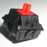
A mechanical switch (the word mechanical has nothing to do with mechanical keyboards in this context) is simply a metal contact which can either connect two pins electrically or not. There are other types of switches which are more complicated and have more pins, but we won't deal with them, since they're not used in keyboards.
So how do we connect a switch to an input of a microcontroller? A basic input device detects 2 possible logic states: "0" and "1". A typical practice is to treat voltages close to 0V as "0" and voltages close to the supply voltage (usually 5V or 3.3V) as "1". The problem with a mechanical switch is that it cannot control voltage on its own. It can only control current in such a way that if we connect two nodes of different potentials with a switch, a current will flow if and only if the switch is pressed.
But if we use a resistor, we can convert current into voltage in a very simple way.
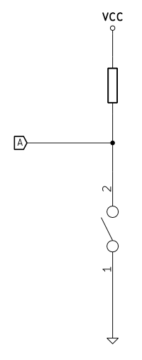
Look at the schematic on the left. When the switch is not pressed (not conducting) no current flows through the switch, so the voltage in node A is close to VCC (less than VCC by the voltage drop on the resistor which is R * I). When the switch is pressed (conducting), the current flows through the resistor and down to ground. Because the resistance of a switch is very low (in the range of hundreds of miliohms), the voltage in node A will be close to 0.
In this configuration the resistor is called a pull-up resistor, because it "pulls the voltage up" to VCC level where there wouldn't be any voltage otherwise (this state would be then called "floating" or high impedance state).
Most modern microcontrollers, however, already have pull-up resistors inside and in most cases you can program the microcontroller to switch it on or off during run-time. So the basic rule when connecting a switch to an input is to connect one pin of the switch to the microcontroller pin and the other pin of the switch to ground. This way the microcontroller will always read a "1" when the switch is not pressed, and a "0" when it's pressed. This may be a bit counterintuitive at the first sight, but that's the most popular solution.
Note that if we leave one of the switch pins unconnected, the switch will not do anything at all, since whether it's pressed or not, it will not affect the electrical state of the microcontroller's pin. We are going to use this property when building the matrix.
The matrix principle
The basic principle of a keyboard matrix is that we connect more than one switch to a single input of a microcontroller.
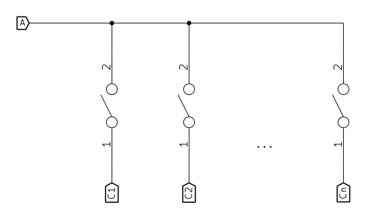
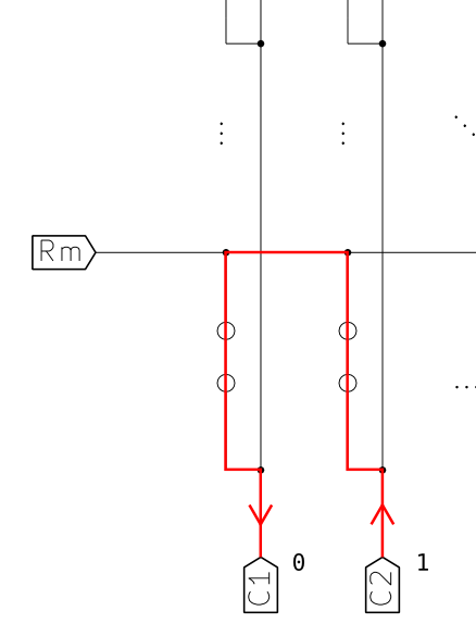
We can use transistors or properly configured microcontroller outputs to connect only one switch to ground at a time, while the others are floating. The other pins of every switch are connected all to one input of the microcontroller. I omitted the pull-up resistor in this circuit, assuming that there already is one inside the input circuitry of the microcontroller. We "turn on" one switch at a time by connecting it's pin number 1 to ground, and we can use the input to read it's state from pin number 2. The other switches connected to this input don't change it's state, because their pins number 1 are not connected anywhere at that time. The circuit on the right illustrates this idea. A is the only input and C1 ... Cn are outputs. One of the outputs set to logic "0" means the pin is actually connected somehow to ground inside the chip, and that also implies that the current will always flow into this pin (as shown in basic principle one). Now when the switch connected to this output pin is pressed, the input A is pulled to ground through the switch, and its state becomes "0". Pressing other switches doesn't change anything, since their other pins are not connected. When we want to read another switch, we change the output pin which is set to "0", so that always just one of them is set like that.
This configuration (where an output is either connected to ground or not connected at all) is called open-drain (OD) (or, historically, open-collector (OC)). I used a simplification here, in fact the pin can't be not connected at all unless it's mechanically disconnected, but for basic digital I/O this assumption is good enough. Most microcontrollers allow the programmer to configure the output pins to work in OD mode. But what happens if we don't have that option? The other possible configuration is push-pull mode and it's more common these days. This means that in the "0" state the pin is still pulled low (to ground), but when the output is set to "1", the pin is pulled to VCC, so it's actually able to supply current, instead of being floating.
What does that change in the matrix design? Well, if we're not going to press multiple switches at the same time, then nothing. If we do, just imagine this situation in the above picture. By pressing any two switches, you electrically connect two of the bottom outputs with a simple loop. If one of them is "0" and one is "1", then current starts flowing from the output which is set to "1" to the one set to "0". Because there is no limitation of this current (no resistors), not only can the circuit become unstable, but it can actually cause the chip to blow. Needless to mention it would be hard to reliably read the state.
Adding more rows
You can think of this example as a one-row matrix. Now what we need to do is extend it with more rows. If we can share one input pin between a whole row of switches, we can also share each of the outputs between a whole column under the condition that each of the switches in a column is connected to a different input.
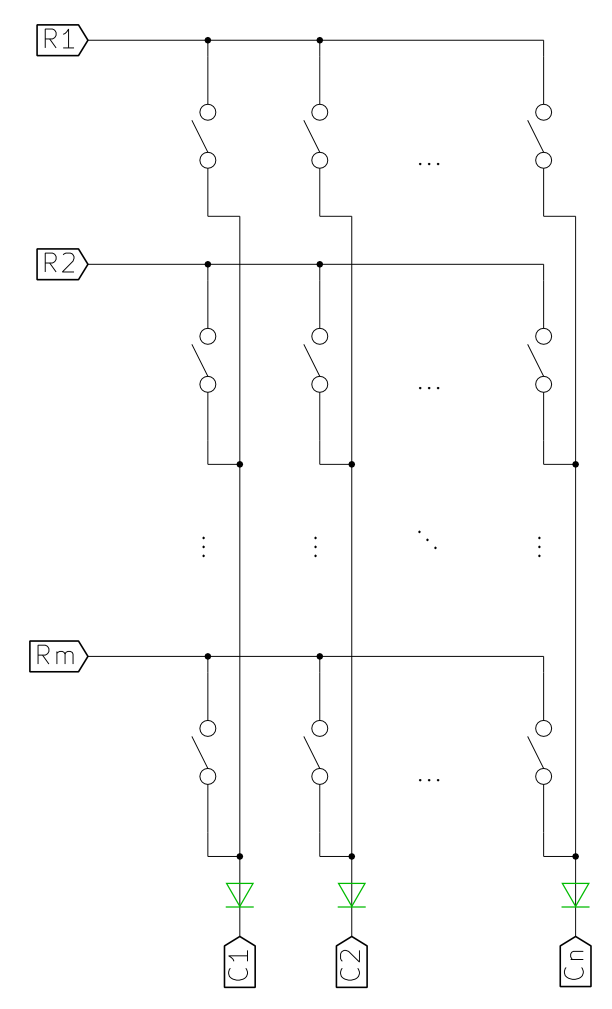
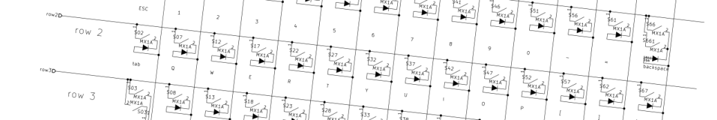
If we arrange the switches to form a regular matrix, this condition is automatically met. And the image on the left shows how it looks for a matrix of n columns and m rows (ignore the green overlay for now).
The way such a matrix is read is simple. We read it one column at a time. The column to be read is selected by connecting one of C1 ... Cn to ground (by setting the output in OD mode to "0"). Now each of the rows R1 ... Rm can be used to read the state of one switch in the selected column. The switches in other columns will not interfere even if they're pressed, because their other pins are floating (or in Hi-Z state, as it's called in electronics).
After a whole column is read, we can go on to the next one by changing the pin being pulled down. A matrix scan is completed after all columns have been read. If this is done fast enough, the intervals between probing columns become unnoticeable even for very fast typists. Even when having just a 16MHz microcontroller, we can easily scan the whole matrix thousands of times per second, whereas the fastest typist on hi-games.net typing test achieves 203 wpm which equals slightly less than 17 keystrokes per second.
Designing a keyboard to use a matrix decreases the number of pins required to read all the switches. Of course in order to decrease this number to the lowest value, we need to design the matrix in such a way that the number of columns is as close to the number of rows as possible. In the perfect situation, where the number of switches is n², the best we can achieve with a matrix is 2n pins. However, in most situations the matrices are not designed to use so few pins, since usually the microcontrollers have more of them to spare. Trying to optimize a matrix like that can be hard, because it may lead to a mess when routing the final board. It's usually much more convenient to try to follow the physical placement of the switches, which means that for standard computer keyboards the easiest matrix to design will have only 6 rows, and some number of columns depending on the layout. This solution is very sub-optimal with respect to the pin count, but at least easy to route.
What if we don't have OD outputs?
You could ask what if the outputs of the microcontroller of choice don't have OD mode. Well, we already know what may potentially happen and that it's not a good idea to strong pull-up any of the outputs (that means "connect" to VCC). There are various ways to solve this problem including special OD output buffers and even shift registers with OD outputs to even further decrease the pin count. But there's one very popular solution among computer keyboards (maybe more in the old times, actually).
The problem with push-pull outputs controlling columns appears when two switches are pressed simultaneously in the same row and while the column in which one of them is is being scanned. The current flows from the output set to "1", instead of Hi-Z, through the other switch, then through the one in the scanned column and down to the output set to "0". This can result in anything from not being able to reliably read the state of the keyboard to the chip being destroyed.
But there is an easy cheat we can use to convert push-pull outputs to OD-like ones if we really have to and I have seen this solution in many keyboards of the old-era. Because the output (column) pins only need to sink current and never source it, we can use diodes to limit the direction of currents. A diode is a simple device which allows the current to flow in only one direction. The arrow in the electrical symbol signifies the direction of current. By inserting a diode between every column pin and the column wire (which later goes to every switch in the column) we can only allow currents to flow into the pins. This way the pin set to "1" will never source current, and this nearly makes it an OD pin. Of course this isn't real OD, but it solves the current loop problem in a keyboard matrix. Go back to the first matrix circuit, but take into account the green overlay this time to see how this solution looks.
Of course to limit the number of diodes used you can try to decrease the number of columns at the expense of the number of rows, and if that doesn't fit the physical layout of the keyboard, then "rotate" the matrix 90 degrees (swap rows with columns). The possibilities are unlimited. But because of a great variety of easy to use hobbyist-friendly microcontrollers, this approach will almost never be used in hobby keyboards. And fortunately so.
Ghosting
If you're into keyboards, you must have heard that word before, and it seems it's a frequently misunderstood term in the keyboard world.
We've already seen how pressing multiple keys in the same row may disturb the readings, but that problem can already be considered solved. Now let's see what happens if multiple keys are pressed both in the same row and in the same column.
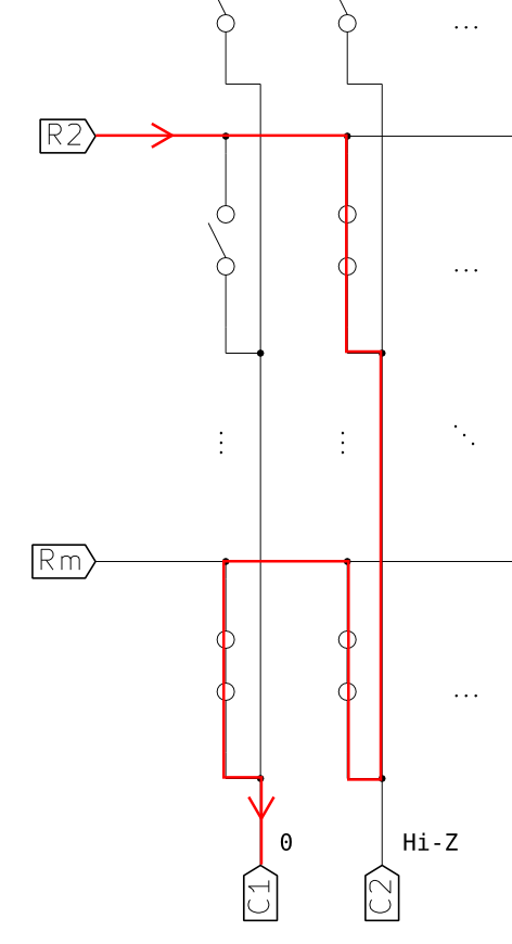
In the picture on the right three switches were pressed simultaneously. Two of them share column 2 and two row m. That means one of those three pressed switches shares both its row and its column with some other pressed switch. This situation is commonly referred to as ghosting. Suppose we're currently reading column 1 (so it's output pin at the bottom is pulled down to ground - "0" state). Because of this characteristic setting of pressed switches, even though the remaining switch (top-left in the picture) is not pressed, the state of the R2 line is "0", because it is pulled down by C1 (currently at "0") through all the 3 pressed switches. This causes the keyboard controller to read the state of that key as "pressed" no matter if it's actually pressed or not. The word ghosting comes from the fact that some key combinations pressed together cause such "ghost" keypresses to appear, even though the keys are not physically pressed.
There are ways to prevent ghosting from disturbing the work of a typist or gamer and they're widely used in all PC keyboards. It is actually possible to detect a situation where a ghost may appear and prevent it from happening. Because a regular person is not able to press or release 2 keys at exactly the same time, with fast enough scanning we can assume that between two scans of the entire matrix no more than one key will change its state. This way the keyboard controller can process one keypress at a time and look for situations where 2 or more keys have become pressed at the same time between two scans. Assuming the keyboard is scanning fast enough not to allow such situations to occur willingly, their occurrence means that one of the newly pressed keys is a ghost. In such a case the keyboard should ignore both these presses and it's the safest to wait until they're both released before sending any state changes to the PC.
A different approach is to detect situations where that "third" key is pressed and suppress it and any further keys until it's released and situation is back to normal. To use this approach, the firmware must remember which keys are pressed (which it normally does anyway) and disallow keys whose both column and row already have a pressed key in them. With some smart coding it shouldn't be necessary to block all further keypresses except for the ones that cause the issue unless they break the rule again. If the keyboard controller blocks every key whose both column and row already have a pressed key, some keys will not be registered depending on the state of other keys. This situation is commonly known as jamming. The term makes sense if you think that it's the other pressed keys that cause some keys to stop working, somehow "jamming" a part of the keyboard.
From the user's point of view, they can always press all keys in a column at the same time (if they are not pressing keys in other columns), but they can press keys from the same row together only if there's at most one key pressed in every key's column. The same goes for pressing keys in the same column. Other pressed keys are only allowed if they're in rows other than the ones already "taken".
The terms ghosting and jamming are often confused for reasons beyond my imagination, since they seem rather intuitive to me.
It's not possible to have neither ghosting nor jamming in a keyboard which uses a matrix like the ones shown above. Since ghosting is rather unacceptable for a regular user, virtually all rubber dome vendors use some anti-ghosting approach which introduces jamming. How to design a matrix in such a way that jamming disturbs the least, and common key combinations do not cause jamming is a good topic for a book and it's the reason the matrices in mass-produced keyboard are so messy and jammed (pun intended).
Diodes on all switches - the ultimate solution
If you look back to the ghosting example circuit, you can see that the culprit is the lower-right switch.
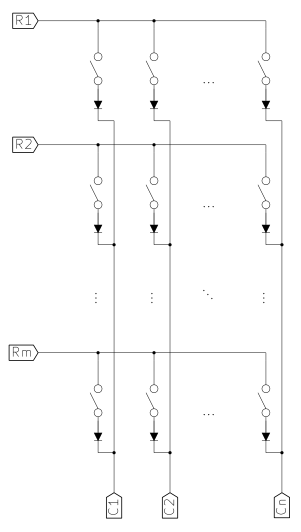
But this switch is the only one where the current flows "up" in this situation, and because we don't need any currents going up to properly read the matrix, we can use diodes to allow the current to flow only to the column outputs at the bottom of the circuit. Unfortunately, this requires one diode for every switch. As for the direction, you should already be able to tell that in this particular example, they have to conduct the current "down", so their cathodes (pointy sides) should face the outputs (columns), whereas the anodes should point at the inputs (rows). Which side of the switch the diode is on does not matter as long as it's properly biased. Just remember that in the approach presented the current always flows from inputs to outputs. This is by the way what always happens with pulled-up inputs and OD outputs.
The presented approach limits the current to flow only "right" and "down", so it keeps loops from appearing when multiple keys are pressed. This is also the only design which allows for full NKRO keyboards. Though it may seem obvious, it might also be worth noting that using a diode with every switch eliminates the need to use OD outputs, since the diodes in series with switches cope with the circuit shorting problem just like the solution with one diode per column.
Rollover
I know this article is already very long, but I think I just need to add this last chapter to make it complete. Rollover is the ability of a keyboard to support multiple keypresses at the same time.
xKRO
KRO stands for key roll over and it normally goes after a number. So it can be for example 2KRO, which means 2 key rollover. A keyboard has x key rollover if and only if it can support 2 keys pressed at the same time no matter when it happens and which keys they are. Most rubber dome keyboards sold these days have 2KRO. This does not, however, limit the number of pressed keys at the same time in all cases. It only says that the keyboard is guaranteed to always be able to support x keys at the same time.
Depending on the matrix layout and controller used, 2 keyboards with 2KRO may behave very differently. Some may always register only up to 2 simultaneous keypresses, and some will easily register more. In this case 2KRO might be declared just because there are some key combinations (preferably uncommon) which will prevent some other keys from being pressed at the same time. Since this means there are combinations of 3 or more keys that can't be pressed together, the company declares just 2KRO.
NKRO
The term NKRO means n key rollover and it's used to describe a keyboard that can support any combination of keys pressed together no matter what. Remember though that there's a difference between NKRO of the keyboard matrix and NKRO of the very keyboard. Whereas just the matrix implementation I showed in this article always supports NKRO with correctly written firmware, this is not necessarily the case for the keyboard which uses such a matrix. This is because of various limitations of the communication ports used by keyboards and because of the vendors cutting costs here and there. I will try to describe the problem of NKRO in PS/2 and USB in the further parts.
Summary
This might have been a long read, but the concept is not so easy at all, especially for a non-electrical engineer. I hope I've explained it clearly, anyway I was trying to be as clear as possible. Because of that the article might be boring for some of you, but if you are into electronics, then most probably you needn't have read that at all;)
Anyway, please let me know if this was of any value to you and if it makes sense to write future parts and I'll start working on the next "episode".
Very nice overview! Looking forward to the next articles in this series 🙂 Will you touch components such as the Phantom PCB and the Teensy controller? In any case - very cool explanations.
Thank you.
I hope more will come after this one. I don't know what I'll cover yet, but most probably the Teensy will appear somewhere.
Now i saw the other posts, about the GH60 PCB 🙂
I suppose you are doing the tutorials in the same pace you will be actually building your own ("dream") keyboard. It will be really really something to see all the steps involved (from the PCB drawing software, design ideas perhaps, some personal decisions, to the end product); it can be a very nice source of inspiration/information for different projects. I'm sure many people (like me) would want to design their own style keyboards, but they are lacking some of the information, at one point or another in the making process. Your howto could change that 🙂 E.g. i live in Europe, i don't want to order a ready-made PCB, but if i have (or even better, if i learn how to make) the schematics of one, i could send it locally to a specialized low-cost company to build it for me.
This was very helpful and gave me a deeper understanding of matrixes. I would love to read a Teensy article from you and specially if the main topic would be 2.0. There could be many subject to write about such as: "best matrix for nkey layout", "adding LED control", "NKRO implementation" and as well the main parts with defining the matrix and adding layers and macros to your mapping. Basic understanding of code and different files would also be interresting.
Hurrah, that's what I was exploring for, what a material!
present here at this blog, thanks admin of this website.
So I am a little confused on the diode wiring. In this example, http://geekhack.org/index.php?topic=20898.0 and this example http://deskthority.net/workshop-f7/brownfox-step-by-step-t6050.html they both connect the black side which seems to be the cathode to the rows and the other side connects to the switch which in turn connects to the columns. That is the opposite of what you say is the right way to do it, so I am just looking at this wrong or does either way work?
Yes, the black side is cathode.
You can connect it any way you want if you have configurable pins in your microcontroller.
In general, it's better to configure it in such a way that you can read as much as possible from a single line - so you want to select rows and read from columns, not the opposite, because the opposite is slower as there are more columns than rows.
I think I showed the opposite example, but it doesn't really matter. As long as you can configure the pins, you can put the diodes in any direction (but all the same) and you'll figure out a way to read it.
i can't understand the diode explanation.
let's say i have a controller with 4 pins, and i'm using it for a 2x2 matrix.
1---sw1---sw2
2---sw3---sw4
`3 `4
if input 1 and 3 are pulled down, controller assumes sw1 is pressed.
but if i press sw2, sw3 and sw4... how, with diodes or not, can it know sw1 is not pressed? since all matrix input pins in the controller will be pulled down.
it messed up my glorious ascii art... just imagine the numers around "swx" forms a matrix
Hi,
when you are reading the first column, you are pulling '3 to GND while '4 is Hi-Z. This way you read your inputs 1 and 2, and you get 1 and 0 respectively, which means sw1 is not pressed and sw2 is pressed.
Then you get to read the second column - you pull '4 to GND and leave '3 Hi-Z. Now when you read 1 and 2, you get 0 on both, so sw2 and sw4 are both pressed.
The above scenario works if there are diodes in series with every switch.
If there are diodes just on the lines '3 and '4 or none at all, the fact that sw2,3,4 are pressed together causes both inputs to be connected to GND when when you pull either '3 or '4 to ground - compare with "Ghosting example" drawing in the article.
The diodes fix the problem because pulling works just one way. 0 is read when the current flows from the input to the pin pulled down and that only happens if the diodes are properly oriented on the way.
I hope that explains it.
Hi!
I really appreciated this tutorial and, thanks to it, now I have a better understanding on how the keyboards work.
Now I'm looking forward for the second part, so I'd like to know when it will come out.
Thanks for your attention.
P.S.: sorry for my bad english.
Hi,
thanks for your feedback, Roberto,
I hope it will come out eventually, but I still haven't got down to doing it yet.
It's a pity you haven't done it yet, but when it will come out you already have a reader 😉
hah, thank you very much for this post. I just got a plate of bare switches, and I wanted to make a tiny "keyboard" for specialized functionality. this taught me how to do it 🙂
This is absolutely fantastic!
It's explained really well and the diagrams helped a lot.
It helped me with my current project to build an Arduino-controlled programmable keypad. I didn't really understand how to use diodes to eliminate ghosting.
May I please reference you and this blog when I share my code?
Thanks,
Matt
Sure, go ahead!
I'm glad the post helped.
Hello,
I was wondering, if I want to use a ready made keyboard controller (taken out of a generic ps/2 or USB keyboard) in order to create a small (11-key) keypad for all the keyboard shortcuts in my favourite desktop application, the controller would already have been designed to deal with all these issues, so I need not worry about any of this, right? Or do I?
Thanks,
Mo
Hello,
It Was a nice and wonderful explanation.
I am pause with one minor problem.
My keypad is 4X4 matrix. but i have 4 column and 3 row.
I connect Didoe across 3rd row and 4th row to increase the row.
but it was no working.
please help me...
Thanks..
Hi There, I am very impressed by your way helping others to know ..etc
But my problem is finding who is able to make a simple 4 octaves circuit board that can
allow me to present a new age keyboard for education.
Regards,
alan
Hello Komar
This description of yours is just great! Can't wait for part two and three.
Best regards
andy
Any news whatsoever about "part 2: controller"? (Although I'm having doubts this will ever happen since this is two years old already...)
How to make anything as a computer keyword? What is the basic concept behind it?
like the one below
http://www.toys400.co.uk/raj/8/
Thank you, Michał, for the interesting and comprehensive guide to keyboard matrices!
And, as someone said, the best way to understand something clearly is to translate it to the different language. So, let me introduce the Russian version of your article!
And yes, patiently waiting for the next part 🙂
firerock,
that is awesome! Thanks for spending so much time and effort.
Now I should finally do the second part!:D
Could you provide a link label in Russian so that I can put it at the top of the page and link to your translation?
Here it is:
Как сделать клавиатуру — Матрица
I've posted it to the Russian IT-blog called Geektimes.ru: https://geektimes.ru/post/276358/
Thank YOU for the great job; comparing to it, my deed is almost nothing 😉
thanks for a brilliant explanation. it would be very interesting to see a further section that gives example of optimal matrix design in the sense of minimising necessary pins. I get the principle (8 pins can support 4x4 = 16 switches, or 5x3 = 15 switches, or 6x2 = 12 switches - if that's correct 🙂 ) and can sort of visualise an optimal wiring of 8x2 switches in 4x4 mode, but since you've done such a beautiful ob explaining the basics.... 🙂
Another interesting extension would be to review the various micro controller options available.
Stephen,
thanks for the warm words and your ideas for the future parts of "How to make a keyboard".
I hope I'll use them when making next parts in the future.
Best regards,
Michał
This electronics description of a keyboard is beautiful! You really know and enjoy your stuff! Thank you.
Thank you - this article is very very helpful. Now when I look down at my keyboard I feel I can understand it a bit better 😀
I am using a HHKB pro2 keyboard. It has 5 rows in its layout. If it's a matrix design I guess there are 5 columns with 14-ish rows?
x1a0,
I't hard to say how the matrix on HHKB is organized, but it is not uncommon for matrices to have nothing to do with the physical arrangement of the keys. As long as there's enough space on the PCB or membrane to route the connections, the electrical matrix can be arranged to be as close to square as possible to minimize the number of control pins necessary.
Thanks for your feedback and best regards,
Michał
Fancy reading. Certainly indepth and detailed post.
I would love to read more in the future.
"How to design a matrix in such a way that jamming disturbs the least, and common key combinations do not cause jamming is a good topic for a book" can someone direct me to one or two matrix designs that work the best? Please do not reply with "just have diodes under every key" because that is NOT what I am looking for. I am looking for matrix solutions that major companies use to save money but that still will recognize keys most of the time in regular typing.
100 diodes are like 63 cents on mouser. Most companies would gladly add that cost and be able to advertise NKRO, most mechanical keyboards are around $80 anyway.
Hey Komar, this article is great! I recently tried to rebuild an old broken electric piano keyboard (http://randomprojectlab.blogspot.com.au/2016/10/electric-piano-part-1-turning-old-piano.html) and I used this as a reference to understand what was going on.
Looking forward to any updates on this article.
Hi mit-mit,
I'm glad to know it was useful to you.
Great keyboard project BTW!
I had to stop at paragraph 2 of Why Matrix.
I cannot and will not REVISE OHM'S LAW.
lol
In British English, revise means to reread work done previously to improve one's knowledge of a subject. No one is telling you to alter ohm's law.
@Andy I wouldn t think you would need to turn a keyboard like that into a matrix, unless you mean you are customizing the keyboard to be a custom input device for something other than a computer.
Hi all,
Using matrix with higher dimensions can reduce even more the number of pins necessary. For example using a 4D matrix of 3x3x3x4 allows for 108 keys using only 13 pins. I'm still working out the details, but in principle to allow NKRO three of the four dimensions have to be put on the rows, thus resulting in 27 rows and 4 columns where every keypress is read using three pins in parallel. Puting in in the perspective of Teensy 3.2 there are exactly 13 digital holes on one side, and with the 27 colums there's a full read cycle in about every 0.1 ms (10k read cycles/s).
Sz
Hi Sz, please I'm really interested in this your 4d matrix keyboard idea, and I will like to know about your achievements concerning this subject.
Hi Proflyn,
after crunching some numbers (combinatorics is difficult :D) I settled for a 3D matrix of 3x6x7 that uses the same 13 pins, but allows up to 140 keys.
I only needed 84, but you can see the idea here: //frozenpuppet.eu/keyboard/matrix.jpg .
For the and gates I use SN74HC11N chips, which have 3 and gates each. I abandoned 4D matrixes as they need way more and gates and programming.
This is so useful and I like your style of developing techniques one at a time. The text is so easy to understand and I learned some terminology in between. Thank you very much.
look this klawiatura.wordpress.com/
2 potenciometer, no switches for typing in any chars language (diacratic some time uses)
Nice. One-page article says it all. =) I have now the usb keyboard circuit. How to distinguish the input and outputs here? I mean the two sections: the columns and the rows?
The middle LED is forward biased and therefore it lights. All other LEDs are either reverse biased, or they have the same voltage (positive or negative) to their both leads, and therefore they do not light. This way, someone can control for example 64 LEDs each one separately, with an 8 matrix, using only 16 outputs from a microcontroller.
thanks for the post, very helpful for me 🙂
Hi,
I'm building a laptop keyboard tester (based on Arduino) and would like to thank you for all the information you have offered here.
Hi,
I've found some diagrams that use a diode in every single key, instead one diode per column.
There is a good reason for that?
Thanks in advance!
lsgxzi
3syufo
b4inqp
f1hylt
3qrp0o
0x8u6t
h8093r
gvz8yv
df257g
kcgp6z
iumzez
h3399o
qxc50i
smsa9x
r838pn
v5t8yu
3opiyt
fbe2a9
s7jj6p
zlydo7
85a96j
b2z3st
jccwa1
lte9hf
un6dlw
5sqxm3
5o4vj3
1bqw2d
vr9q6v
wdhdht
d2xw23
yucxz2
xrgjeg
n8ays5
fa9ory
mttuyn
lcguxs
y4jd1q
ewtije
hs12d2
9runy8
z5c23s
l0x658
rxexka
8agim2
brr08j
y8ew5q
wlyzpq
yijlla
2cwhyu
kj8kc7
jd40nt
jmk519
1spbwe
y8jwkx
ujzym5
xchp4g
btmlkt
mqpgxj
ej02aj
1cyjme
c8v1g7
6lwfft
sa27yn
pwtps4
i0sqyb
hrk8w8
vveyi1
xdvehe
cqab1i
f5v7gc
81h9sq
i9rlip
8u76v0
8c5j0e
fr4tn0
kwee4t
xjeb78
jdepo7
efkbxx
ygq7uz
3oybx5
dofcbo
o7ae0x
nj4epk
oiqevb
l22yts
pggt8y
uqgjb2
75bdst
ztcqid
mxq4qz
xp62as
lps5jz
huf4ru
ueqwqa
y60r4a
nvia47
x1elqb
vdd412
1vupe0
uat1op
ov1089
v9lr4h
n2sncm
4gys95
v9b1wj
80hjr3
8fh8jt
mmg5bh
az370o
ixq9va
9b5nhb
a0pkwf
oc7wrx
rrcwla
iz0os1
4pns4r
z0sqoh
5mew2y
10ojtg
rckhux
l34rg2
ft42x6
t8w0ap
817x68
3tkgk9
k4xekm
nkinu4
jhdh2t
bgokp6
i919lm
httyo7
zk55ty
wjbv23
jzgl1u
563092
gb7r2q
fmop8v
zo6pwz
nv3mo9
7jm0de
27td0e