This is part 2 of reverse-engineering the LCD driver inside a COB device on a cheap "9999 in 1" videogame. Make sure you also check out part 1 here: 9999 in 1 reloaded - part 1.
Driver analysis - part 2
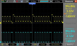
Let's look at the last plots again. Yellow is common signal, cyan - segment signal, and magenta - difference across pixel. This time I measured them with the LCD disconnected, so they should look a bit nicer.
After assigning the roles to signals (commons and segments) it gets much easier to find out what's going on. Once I got to understand how an LCD works, the signals made much more sense.
The segment signal oscillates either between 1.2 and 2V or between 0 and about 3.4V, but it's always a square wave in phase with the common signals (except when they filp one edge). Let's see what voltage this signal generates across a pixel:
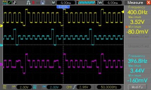
When a particular group's common signal is not flipped, the voltage across a pixel is between -1V and 1V, so this is presumably not enough to twist the crystals. But even when the common signal is flipped (and also has a bit higher amplitude) - see the left picture, the voltage across a pixel is kept below 2V. I assume this is still not enough to make a visible dot.
This implies that the low-amplitude oscillations are used to drive a pixel off. The levels are apparently chosen in such a way that such signal does not turn a pixel on either when a different group is selected or when it's the pixel's group that's selected and the pixel should be off.
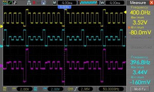
Now if you look at the right image, you can see that when a pixel is to be turned on, on the segment line appears much higher amplitude - over 3V. This wave is still in phase with the base square wave, so all the pixels which aren't in currently selected group get a signal between -1 and 1V, and in consequence they're still off. But one of the groups is selected, so its common signal is not only flipped but also has a higher amplitude. This means that for the on-pixels in currently selected group the voltage is greater than 3V (and then lower than -3, of course). And this seems to be the only condition under which a pixel is actually driven high.
Frame grabber
It seems there is a way to read the contents of the screen much more easily than sampling every pixel very fast. The only part of the common signal we're interested in is either the preshoot or overshoot of the rising flipped edge. These are the moments when we can actually read the values of all pixels in a particular group. In the first case, a pixel will be on if its segment signal is high. In the latter, when its low. A pixel will be off if the signal is "in between", that is somewhere between 1.4 and 2V, as I mentioned before. This means that its enough to use analog comparators to preprocess the signals, which will be later fed to a microcontroller. But this is not the simplest (or cheapest) solution.
Decoding common signals
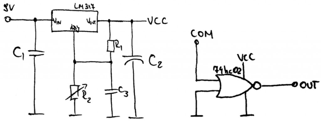
I took a 74hc02 - a standard quad nor to see if I can find such supply voltage for which the gate will recognize the overshoot as binary "1" and everything else as a "0".
 The power supply part comes from LM317's datasheet. The values of parts R1, R2, C1, C2 can be found there too. C3 is 100nF for additional voltage stability. COM is the common signal input, OUT is the output.
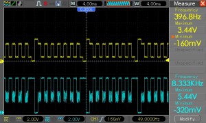
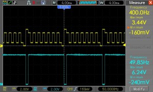
I set the pot to get about 4V VCC and started gradually increasing the supply voltage hoping to set the threshold voltage somewhere just above 3V. The result at the beginning was rather obvious, the most important parts of signal were ignored, but I was left with a nice binary signal, which could be used to detect group selection, although this would require measuring time.
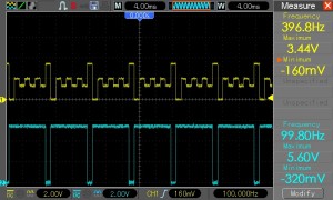
In the following left picture you can see when I managed to set the threshold voltage somewhere at the high level of the base square wave, so the output started to go weird. Later, at 6V - the chip's maximum, it worked!
Decoding segment signals
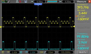
I connected the other (segment) signal to the same device and probed at VCC = 6V. Obviously this was not the expected results, as while the voltage on the common signal is at the highest peak, we expect 0V on segment signals for on-pixels and something higher for off-pixels.
I had to go down to as low as 2.6V to achieve a satisfactory result. And it's worth noting, that the input voltage is over 1V higher than the supply voltage of the device, so this is definitely not considered good practice.
If a NOR works well, an octal inverter or buffer should as well. At least that's what I'm assuming so far, as this would require just a couple of DIP16 chips.
Now it's easy to actually read pixels from the driver. For every group, wait for a low state on its preprocessed line, then probe the segment lines. High means on, low means off. The only thing that has to be taken into account is that the levels of the signals are different, so whatever device will decode is has to be able to recognize a "1" at both 2.6V and 6V... And it has to have enough input pins.
Will a 74hc166 parallel-to-serial buffer's inputs work as well as those of a simple gate? Or will it be necessary to use two stages?
Wait for part 3 and get to know!
Dear Friend
I am a Brazilian Electronic Technician, and I have a new blog that talks about Brick Games.(LCD Handheld Tetris Game) In my blog have several internal and external pictures of various models of Brick Games, including Apollo branded versions, and an explanation about the (older) and most common Brick Game's architeture, E-23, used in the years between 1992 to 1999.
When I see your (partial) 9999 in 1 PCB photo, (WL-801R3), I recognized this as a variant of the E-23 architecture. It seems to have a 15k resistor which did not appear in the Picture...
Please read the topic about E-23 architeture on my blog, and download the DATASHEETS
http://brickgame.blog.com/informacoes-tecnicas-e-manutencao/
My blog is in Portuguese language, but you can use Google Translator.
I believe the datasheets that I have made available will help you in your work.
Hi,
thank you very much. I'll translate and check out your blog. Especially the datasheets you have there seem to be interesting and they explain a bit of how the game works.
The resistor on my unit is 27k
Thanks again,
Michał
When will part 3, and where I can load firmware of Brick Game?